Do you want to buy antibiotics online without prescription? https://buyantibiotics24h.net/ - This is pharmacy online for you!
F74g.qx
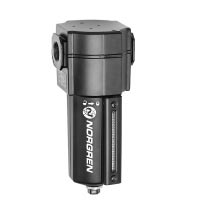
EXCELON® 74 General Purpose Filter 3/8", 1/2", 3/4" Port Sizes
● EXCELON design allows in-line or modular installation
● Quick release bayonet bowl
● Highly visible, prismatic liquid level indicator lens
● Optional mechanical service indicator turns from green to red when the filter element needs to be replaced
● Optional electrical service indicator provides electri- cal output when the filter element needs to be replaced - see page N/AL.8.900.920
● Modular installations with EXCELON 72, 73, and 74 series can be made to suit particular applications Technical Data Ordering Information
See Ordering Information on the following
Transparent bowl: 10 bar (150 psig)Metal bowl: 17 bar (250 psig)
Transparent bowl: -20° to 50°C (0° to 125°F)Metal bowl: -20° to 80°C (0° to 175°F)
* Air supply must be dry enough to avoid ice formation at temperatures below +2°C
ISO Symbols
Particle removal: 5, 25, or 40 µm filter elementAir quality: Within ISO 8573-1, Class 3 and Class 5 (particulates)Typical flow with a 40 µm element at 6,3 bar (90 psig) inlet pressure
and 0,5 bar (7 psig) pressure drop: 83 dm3/s (176 scfm)
Manual drain connection: 1/8"Automatic drain connection: 1/8"
Automatic drain operating conditions (float operated):
Bowl pressure required to close drain: Greater than 0,3 bar
Bowl pressure required to open drain: Less than 0,2 bar (3 psig)Minimum air flow required to close drain: 1 dm3/s (2 scfm) Manual operation: Depress pin inside drain outlet to drain bowl
Nominal bowl size: 0,2 litre (7 fluid ounce)Materials:
Transparent: Polycarbonate with steel bowl guardMetal: Aluminum
Metal bowl liquid level indicator lens: Transparent nylonElement: Sintered plasticElastomers: Neoprene and Nitrile
Our policy is one of continuous research and development.
N/AL.8.200.100.01
We reserve the right to amend, without notice, the specifications given in this document. Typical Performance Characteristics FLOW CHARACTERISTICS FLOW CHARACTERISTICS PORT SIZE: 1/2" PORT SIZE: 1/2" ELEMENT: 5 µm ELEMENT: 40 µm INLET PRESSURE: bar g (psig) INLET PRESSURE: bar g (psig) 6,3 8,0 10,0 (58) (90)(116)(150) (90) (116) (150) PRESSURE DROP PRESSURE DROP Ordering information. Models listed include ISO G parallel threads, automatic drain, metal bowl with liquid level indicator, and a 40 µm element.
* Typical flow with a 40 µm element at 6,3 bar (90 psig) inlet pressure and 0,5 bar (7 psig) pressure drop. Alternative Models Accessories
N/AL.8.200.100.02
Our policy is one of continuous research and development.
We reserve the right to amend, without notice, the specifications given in this document. Dimensions mm (inches) 80 (3.15) 37 (1.45) 74 (2.89) Optional Service Indicator 60 (2.36) 25 (1.00) 230 (9.06) * 246 (9.69) * 161 (6.35) 177 (6.95) Automatic Drain 1/4 Turn Manual Drain
* Minimum clearance required to remove bowl.
† Dimension for alternative electrical service
Bracket Mounting Mounting Bracket Quikclamp and Quikclamp Wall Bracket
Use 5 mm (3/16") screws to mount bracket to wall.
Use 6 mm (7/32") screws to mount bracket to wall
69 (2.72) 24 (0.95) 51 (2.01) 51 (2.00) 79 (3.11) 101 (3.98) 82,5 (3.25) 37 (1.46) 25 (1.00) 50 (1.97) 61 (2.40) Bracket Kit Reference 20 (0.77)
Our policy is one of continuous research and development.
N/AL.8.200.100.03
We reserve the right to amend, without notice, the specifications given in this document. Service Kits
Service kit includes louvre/element seal, drain seal, bowl seal.
These products are intended for use in industrial compressed air
systems only. Do not use these products where pressures and temperatures can exceed those listed under ‘Technical Data’.
Before using these products with fluids other than those specified, for
non-industrial applications, life-support systems, or other applications notwithin published specifications, consult Norgren.
Through misuse, age, or malfunction, components used in fluid power
systems can fail in various modes. The system designer is warned toconsider the failure modes of all component parts used in fluid powersystems and to provide adequate safeguards to prevent personal injury ordamage to equipment in the event of such failure. System designers must provide a warning to end users in the system instructional manual if protection against a failure mode cannot be adequately provided.
System designers and end users are cautioned to review specific
warnings found in instruction sheets packed and shipped with theseproducts.
Water vapor will pass through these units and will condense into liquid
if air temperature drops in the downstream system. Install an air dryer ifwater condensation could have a detrimental effect on the application.
Our policy is one of continuous research and development.
N/AL.8.200.100.04
We reserve the right to amend, without notice, the specifications given in this document.
Issued March 2004 CUPRINOL TRADE LOW ODOUR 5 STAR COMPLETE CT636 WOOD TREATMENT PRODUCT INFORMATION Typical Use Cuprinol Trade Low Odour 5 Star Complete Wood Treatment is a colourless, multi-purpose product for use in the eradication of wood decay, including Dry Rot and all forms of wood-boring insects, it also protects against future attack. For use indoor
Arthur J Henn, AIA A r c h i t e c t , L L C 409 North Avenue East 9 0 8 - 7 0 9 - 6 7 3 4 ( P ) S e c o n d F l o o r 9 0 8 - 7 0 9 - 6 7 3 8 ( F ) C r a n f o r d N J 0 7 0 1 6 Art@AJHarchitect.com Agreement Between Owner and Architect This Agreement is made on: January 1, 2010. Between the Owner: For the following Project: Additions and alterations to the residence at
 EXCELON® 74